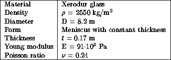


The rms surface error, hence the total wavefront aberration incurred by a real mirror under the measured pressure fluctuations may be computed from the modal pressure coefficients and the structural parameters of the mirror. This computation was done for the case of the VLT primary mirror, which has the following main characteristics:

The VLT mirror is supported by three hydraulic whiffle-trees,
each acting the same pressure on 50 points over a 120 sector. The centers of the three sectors constitute
the three virtual fix-points of the mirror.
150 active optics actuators are integrated into the hydraulic
supports and are astatic, as they only
produce controlled forces and are not reacting to external loads.
The predominant deformations produced by external forces are the elastic eigenmodes of the mirror with the lowest eigenfrequencies. The deflections in these eigenmodes are proportional to the corresponding components in the pressure field, with scaling factors which are inversely proportional to the square of the eigenfrequencies of these modes. The wavefront aberrations generated by the wind pressure fluctuations can then be computed as the sum of the lowest eigenmodes generated by the corresponding pressure fields and the reaction forces on the fixed points. The computation method is rather complex and is described in [Noethe 91]. The computation for the VLT mirror was performed by L. Noethe of ESO and is reported in [Noethe 92]. Hereby we will only present some main results and draw their general consequences.
The following table shows the dependence of the rms
of
the wavefront aberration in the main optical modes
on the zenith angle  of the dummy
for
  . The data are from the measurements
1 to 7 in the NTT (see section
  of appendix
  )
and are normalized to an external wind speed of 10 m/s:

The bulk of the wavefront aberration is contained in the astigmatic mode which is very similar to the first eigenmode of the mirror, which has symmetry two.
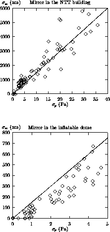
Fig.  shows for all measurements
the correlations between the average
  of the rms
values
of the pressure variations and the
rms
 of the computed total wavefront aberration.
The figures suggest a linear relationship between the two parameters,
independently of mirror azimuth and zenith,
with a factor
  150 in the NTT building and slightly lower
in the inflatable dome.
Recalling also that the modal pressure coefficients were similar in the NTT and in open air, it appears that the normalized modal pressure patterns on a mirror are determined to a greater extent by the disk shape itself than by the particular wind flow field inside the enclosure. Therefore it is possible, at least for the purpose of engineering parametric studies to express the total wavefront aberration simply from pressure measurements with few sensors on the mirror.

Figure: Rms of the total wavefront error versus the
average rms
of pressure fluctuations.
The line represents the relationship  .
.
The relationship
 applies of course only to the VLT
mirror but can be scaled to other mirror dimensions.
Recalling that the displacement of a loaded plate
is proportional to
  ,
for a mirror of arbitrary stiffness, diameter
and thickness, supported on three equidistant
virtual points, one obtains:
Recalling that the wavefront aberration caused by the pressure
fluctuation consists predominantly of astigmatism, we have computed
by means of the SuperIMAQ program the rms slope error of the optical aberration
  as a function of the wavefront error
  obtaining:

where following the usual conventions  is expressed in
nanometers and D in meters. Inserting equation (
 ) we
obtain:
Another aspect of general interest is the reduction of rms
surface error when the mirror is shielded from the direct
wind approach, as in the inflatable dome (see
fig.  ).
The degree of this protection can be further increased
by raising the inflatable segments.
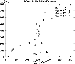
Fig.
  shows the influence of the
elevation of the northern (windward) segment of the dome
on the wavefront aberrations.
\
\

Figure: Rms of the total wavefront aberration in the inflatable
dome as a function of external wind speed
(squared) for different elevations of the northern (windward) sector of
the dome - see fig.  .
.


