

Next: Retractable enclosure
Up: Wind loading on
Previous: NTT rotating building
The cylindrical enclosure selected for the VLT
unit telescopes is presented in section  and
appendix
  .
This type of enclosure retains elements of both the NTT
building (namely the large upside-down-L shaped slit doors)
and conventional domes.
The enclosure structure is essentially an envelope protecting the
telescope with a rotating upper part.
Louvers and other openings are placed along the entire envelope
surface and a proportionally larger volume can be ventilated than in
the NTT.
Wind tunnel tests of this enclosure were performed at the
boundary layer wind tunnel of the Danish Maritime Institute.
The model included the complete enclosure with a fully modeled
telescope inside it at a scale of 1:64 as shown in
fig. 4.12. The tests were run with
several venting configurations of the enclosure:


Figure 4.12: Photograph of the test model
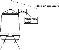
We present here the flow properties measured
at the location just in front of the top ring of the telescope, as
shown in fig. 4.13, which are most determining for
the guiding performance of the telescope.
The test report ([DMI]) describes the results of all the
measurements performed, which included also forces and
torques on the telescope and the pressure distribution
on the enclosure outer surface.
Fig. 4.14 shows the measured normalized values of mean speed,
turbulence intensity and length scale for the various venting
configurations. Fig. 4.15 gives the normalized
fluctuation of dynamic pressure  .
The results show a pattern similar to the case of the NTT when the
flow can pass through the telescope volume (louvers open):
mean speeds decrease sharply for azimuth angles
greater than 20
 ; without windscreen there is a
large increase of turbulence for azimuth angles between
20
 and 40
 .
The fluctuations of dynamic pressure on the telescope
will be largest for an azimuth
  , where the
turbulence length scale drops to about 0.2 of the slit width.
However, when the louvers are closed and the
cylinder surface is air tight except for the large slit
(configurations C-C-O and C-C-20%), the flow cannot pass through the
telescope volume and the speed near the top of the telescope
speed increases with a growing azimuth angle at least until 40 .
Unfortunately no measurements were performed for these configurations
at larger azimuth angles.
Like for the NTT, the data conclude to the need of a 20%
semi-permeable windscreen which will limit high frequency pressure
fluctuations on the telescope by reducing the mean flow velocity.

Figure 4.13: Measuring point for wind loading on the telescope: 4 m (full
scale) in front of the top ring
0.9
[IMAGE ]
Figure 4.14: Cylindrical enclosure: flow on telescope upper part
[IMAGE ]
Figure 4.10: Normalized rms of dynamic pressure
 on the telescope
upper part
0.6


Next: Retractable enclosure
Up: Wind loading on
Previous: NTT rotating building
Lorenzo Zago, lorenzo.zago@heig-vd.ch,
Mon Nov 6 23:33:14 GMT+0100 1995
 and
appendix
  .
This type of enclosure retains elements of both the NTT
building (namely the large upside-down-L shaped slit doors)
and conventional domes.
The enclosure structure is essentially an envelope protecting the
telescope with a rotating upper part.
Louvers and other openings are placed along the entire envelope
surface and a proportionally larger volume can be ventilated than in
the NTT.


 .
The results show a pattern similar to the case of the NTT when the
flow can pass through the telescope volume (louvers open):
mean speeds decrease sharply for azimuth angles
greater than 20
 ; without windscreen there is a
large increase of turbulence for azimuth angles between
20
 and 40
 .
The fluctuations of dynamic pressure on the telescope
will be largest for an azimuth
  , where the
turbulence length scale drops to about 0.2 of the slit width.
 .
Unfortunately no measurements were performed for these configurations
at larger azimuth angles.

 on the telescope
upper part