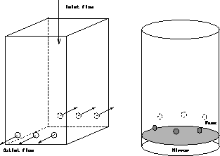
Figure: The CFD "square" model with respect to the actual telescope shape


The astronomical observatory of the University of Geneva is presently developing a new 1.25-m telescope. This telescope is provided with a closed tube as this design solution was deemed best to prevent temperature fluctuations arising in the dome from affecting the quality of the light beam. Still, a ventilation of the mirror surface is planned by mean of active fans mounted around the contour of the tube.

Figure: The CFD "square" model with respect to the actual telescope
shape
The purpose of this preliminary investigation was to quantify at least approximatively the flow conditions in the tube, then to evaluate the mirror seeing of the telescope and the influence of the fans.
The computation was performed with the ASTEC program available at
EPFL.
In order to save time for this pilot evaluation,
the telescope tube has been modeled simply with a square cross-section
1200 1200 mm (fig.
  ).
The last fluid node-plane before the mirror
surface was set at 1 cm from the interface.
The initial temperature was set at 283K with the
mirror at 285K (
 = 2K).
The effect of the fans was simulated by
setting outlet velocities at 6 locations roughly corresponding to the
positions of fans in the telescope (fig.
  ).
Different fan flow rates
were given as input.

Figure: The grid of the CFD model
Fig.  below presents the main results
at three locations 1 cm above the mirror, the height of the first fluid
node-plane. The ASTEC output provides the node values for
mean velocity, temperature and turbulent kinetic energy, from which
the heat flux and turbulence intensity are derived. The local
profiles of
  and the integrated seeing FWHM
  are computed by means of off-line post-processing
according to equations (
 ) and (
 ).
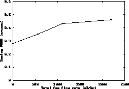
The seeing FWHM averaged over the whole
surface is then plotted in fig.
  .
.
[IMAGE ]
Figure: Mean speed, surface heat flux and
turbulence intensity at three points located 1 cm above the mirror
surface, versus the total airflow rate of the fans.

Figure: Average seeing FWHM
computed over the mirror aperture
versus the total airflow rate of the fans. The temperature difference
between the mirror surface and ambient air is here 2K.
The seeing computed for the free convection case at the "boxed" mirror is lower than for an open configuration. This result is due to the well known fact that the free convection heat transfer rate from a warmer horizontal surface is quite lower when this is enclosed (see for instance [Incoprera], page 517 ff.). However the seeing is not improved by the active flow caused by the fans. In fact the planned fans cannot provide a sufficient mean flow speed to obtain a significant flushing of the mirror surface, while they create large turbulence intensities. One may recall here that turbulence intensity values larger than 0.40 are generally associated to instantaneous flow reversals.
If the fans are maintained, they should then only be used
in conjunction with the daytime air/conditioning system, to enhance
the heat exchange between mirror and air in order to eliminate or
decrease the occurrence of mirror-air  when observation begin.


